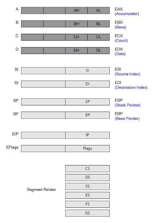
CPU Architecture & Authority Control
General register designations.
______________________________________________________________________________________________
Till physical address & authority control
___________________________________________________________________________________________________
Segment Descriptor : 8 Byte size
Content
___________________________________________________________________________________________________
Segment Descriptor Table
_asm lgdt [GDT]
GDTR
__________________________________________________________________________________________
x64
__________________________________________________________________________________________
━━━━━━━━━━━━━━━━━━━━━━━━━━━━━
explains
Till RAM & Authority control (of Intel Processor)
--------------------------------------------------------------------------------------------
Process → Segment Descriptor → Paging → RAM (physical address)
(segmentation)
--------------------------------------------------------------------------------------------
The address referred to by the process is mapped to an actual physical address through two main parts,
segmentation and paging.
During the memory mapping process, not only the actual physical address but also the access right to the
address is queried.
The segment descriptor is referred to in the segmentation process, and authority information is also written
in the segment descriptor along with address information about the segment.
Base Address (4Byte) : The base address of the segment, segment start address
DPL (2bit) : Privilege level (00, 01, 10, 11)
Privilege level : Call Ring 0 ~ Ring 3
> Ring 0, Ring 3
In case of kernel privilege(ring 0), all operations are allowed, and in case of user privilege (ring 3), only
permitted operations are executed
That privilege control is enforced by the microprocessor.
Intel Added design for permission control from 80286 processor
Windows has used that privilege control since Windows NT.
There are 4 privilege levels (0-3)
Windows uses only two of them, 0 and 3
0 : Allow Full Control, Kernal mode
3 : Allow only minimal privileges, User mode
---------------------------------------------------------
The segment descriptor table is an array of segment descriptors,
The start address of the segment descriptor table is in the GDTR and LDTR registers.
GDTR : Global Descriptor Table Register
LDTR : Local Descriptor Table Register
Get the start address of the segment descriptor table with the GDTR register and,
Six segment registers serve as indexes for segment descriptors.
_____________________________________________________________________________
x86 & x64 GDTR
_____________________________________________________________________________
∴
Segment descriptor table address(GDTR) + Index(segment register) = Segment descriptor
∴
A combination of GDTR register and segment register values determines which descriptor will be
used in the segment descriptor table, and information on the actual physical address, access control,
and authority is recorded in that descriptor.
The microprocessor decides what to allow or block for that address based on that value.
The descriptor and descriptor table must be created at boot time of the operating system that will use
the CPU privilege control function.
______________________________________________________________________________
Segment Descriptor : 8 Byte size
Segment start address, segment size, authority level
(Base Address, Segment Limit, DPL)
Base Address (4Byte) : Segment base address Segment start address
Segment Limit (20bit) : Segment size
DPL (2bit) : Privilege level
Content
______________________________________________________________________________
Segment Descriptor Table
_asm lgdt [GDT]
The starting address of the Segment Descriptor Table is in the GDTR register,
The machine language(assembly instruction) that writes a value to the GDTR register is 'lgdt'
After the operating system creates the descriptor table, the value of the start address must be written
to the GDTR register using the lgdt command, so that the processor(CPU) can know the location of
the descriptor table.
There are GDT and LDT in the descriptor table, and their addresses are recorded by the GDTR and
LDTR registers, respectively.
The GDT must be written by the operating system, and the LDT does not need to be written.
━━━━━━━━━━━━━━━━━━━━━━━━━━━━━━
More
Process permission management (memory access control)
Intel series CPUs have been providing access control functions for a long time, but Windows only
started to use access control with NT.
Intel series processors use the concept of a Ring for access control
The Ring has a total of 4 levels from 0 to 3 (0 being the highest authority)
Internally, each ring is stored as a number (there are no physical rings)
Important tables used by the CPU
GDT (Global Descriptor Table)
LDT (Local Descriptor Table)
PD (Page Directory)
IDT (Interrupt Descriptor Table)
The operating system that wants to use CPU access control and permission control must create the
necessary tables.
Memory Access Control
Memory is,
Segment > Page Directory > Page
Inspection of DPL (Descriptor Privilege Level) value of segment descriptor of Global Descriptor Table(GDT)
(The DPL value means the ring value of the segment)
¯
Check the user/supervisor bit of the Page Directory, If it is 1, all process access is allowed, If it is 0, only
processes with administrator privileges (ring 0,1,2) are allowed access.
¯
Check the user/supervisor bit of the Page (Same as below Page Directory)
___________________________________________________________________________
_________________________________________________________________
System Protection
System protection is very important in a multi-process environment. User programs should not be
able to easily change critical code in the system.
When designing the 80286 processor, Intel put a lot of thought into system protection and devised a
system protection mechanism in the memory management unit(MMU) within the CPU.
Because any program is executed and modified by memory access, hardware system protection is
performed at the memory access stage.
_________________________________________________________________
If you want to develop the OS yourself, (running in protected mode)
Before switching the CPU from real mode to protected mode, the GDT must be written.
(somewhere in memory)
The CPU starts in real mode and is switched to protected mode by the operating system.
(Intel x86)
The GDT may be a design diagram for kernel codes of an OS when the CPU operates in the
protected mode.
(So that the CPU knows where the kernel parts are and in what structure)
GDT, The descriptor table, as the name suggests, is a table(array) of descriptors.
_________________________________________________________________
Segment Register & Selector, Descriptor Register
____________________________________________________________________________
System Internals (developer edition)
▪▪▫


